In modern electronic, communication, and industrial automation systems, cables not only undertake the tasks of signal and electrical power transmission but also have a direct impact on the performance and stability of the entire system. Among them, cable impedance, as one of the important parameters for measuring transmission performance, has a significant influence on signal integrity, energy transfer efficiency, and system reliability. This paper will systematically elaborate on the definition, causes, calculation methods, and application significance of cable impedance, and combine typical examples to illustrate its importance in engineering practice.
Definition of cable impedance
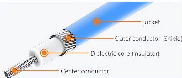
Cable impedance refers to the comprehensive impedance that a cable exhibits when transmitting alternating current signals, especially high-frequency signals. It not only includes the conductor's direct resistance but also the effects of inductance, capacitance, and dielectric conductivity caused by the cable structure and dielectric properties.
In practical engineering applications, the most commonly involved parameter is the characteristic impedance (Z₀). The characteristic impedance represents the ratio of voltage to current when an alternating current signal propagates in an infinitely long cable in a stable form. This parameter is a core indicator for evaluating the transmission performance and matching conditions of the cable.

The causes of cable impedance
The impedance of a cable originates from its internal physical structure and material properties. Any segment of a transmission line unit can be equivalently represented by a distributed circuit composed of the following parameters:
R: Resistance per unit length of conductor
L: Unit length inductance
C: Per unit length capacitance between conductors and between conductors and shielding layer
G: Unit length conductivity of insulating medium
When communication signals propagate through cables, the interactions among R, L, C, and G collectively determine the cable's frequency response and impedance characteristics.

Calculation of cable characteristic impedance
Under high-frequency or ideal lossless conditions, the characteristic impedance of a cable can be expressed by the following formula: Z₀ = √(L / C) where, L is the inductance per unit length, and C is the capacitance per unit length.
Different types of cables have different characteristic impedances due to variations in structure, size, dielectric constant, and shielding methods. Common types include:
• Coaxial cable: 50Ω, 75Ω
Twisted pair Ethernet cable: 100Ω
The importance of cable impedance
Signal integrity assurance
When the signal source, transmission line, and load impedance are matched, signal energy can be efficiently transmitted, avoiding reflection and distortion; if the impedance is not matched, it will lead to reflection and standing wave phenomena, affecting signal quality and even damaging equipment.
High Frequency and Radio Frequency System Stability
In radio frequency communication, video transmission, and high-speed data links, impedance matching is a fundamental principle of design and debugging, which directly affects the signal stability and energy utilization of the system.
Power transmission efficiency
The reasonable matching of cable impedance can effectively reduce power loss, improve transmission efficiency, and ensure the reliability and safety of equipment operation.
Five, examples of the application of cable impedance
Antenna Feedline System: Utilizing 50Ω coaxial cable, matched with the transmitter and antenna impedance to ensure efficient transmission of radio frequency energy.
Television signal transmission: Using 75Ω coaxial cable to achieve the best match between the signal source and receiving equipment.
Computer Network System: commonly uses 100Ω twisted pair cables to ensure high-speed signal transmission and stable network communication.
Six, impedance measurement methods
In engineering practice, the cable impedance can be measured by the following methods:
• Network Analyzer Measurement Method
Impedance analyzer method
• Time Domain Reflectometer (TDR) method: It can be used to detect the impedance distribution and fault location of cables.
Cable impedance is a key parameter that affects signal transmission performance and system stability. By reasonably designing cable structure, selecting appropriate materials, and ensuring system impedance matching, signal integrity and energy utilization efficiency can be effectively improved. Whether in radio frequency communication, video systems, or high-speed data transmission, understanding and controlling cable impedance are core elements in engineering design and application.
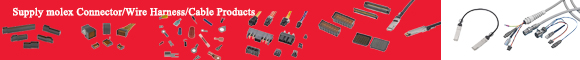
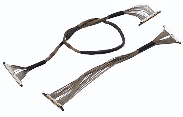
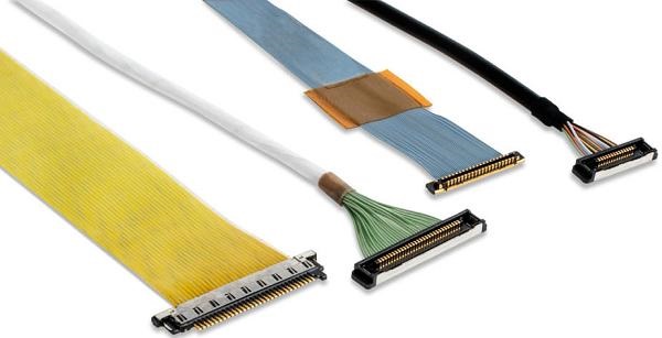
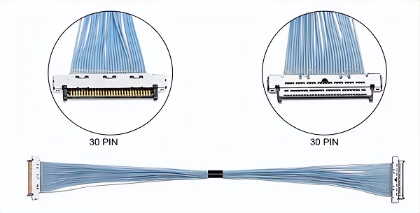
I am[Suzhou Huichengyuan Electronic Technology]Long-term focus on the design and customization of high-speed signal cable harnesses and ultra-thin coaxial cable harnesses, committed to providing customers with stable and reliable high-speed interconnect solutions. For more information or to customize related products, please contact:Manager Yin 18913280527 (WeChat number same)。